Extrinsic Calibration
Rig and Coordinate System Conventions
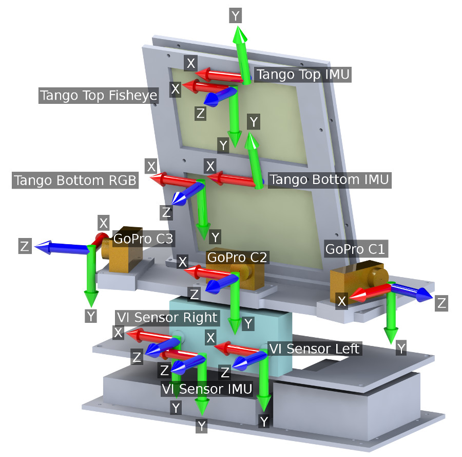
All sensors are extrinsically calibrated with respect to the rig body (B) reference frame (which coincides with the center GoPro C2 camera). For each sensor we give the transform $\cc{\mvec{T}}$ from the rig coordinate system to the sensor coordinate system. A left superscript indicates the coordinate system in which vectors are expressed, i.e. $\cc{\cvec{X}{C1}}$ are the coordinates of vector $\cc{X}$ in the reference frame of camera C1. The transform $\cc{\ctrans{T}{S1}{S2}}$ takes a vector expressed in coordinate system S1 and transforms it to system S2: $\cc{\cvec{X}{S2}=\ctrans{T}{S1}{S2}\ \cvec{X}{S1}}$. For example, given coordinates in the rig reference frame (B), the ones for camera C1 can be obtained via: $$ \cc{\cvec{X}{C1}=\ctrans{T}{B}{C1}\ \cvec{X}{B}} $$.
Transformations in Matrix Form
In the below table, the transform T can be expressed as a 3x4 transformation SE(3) matrix: $$ \cc{\mvec{T}=\begin{bmatrix}\mvec{R}\ \mvec{t}\end{bmatrix}} $$ where $\cc{\mvec{t}}$ is a 3x1 translation vector, and $\cc{\mvec{R}}$ is a 3x3 SO(3) rotation. Note that $\cc{\mvec{t}}$ is expressed in meters, and is given in the coordinate system of the sensor.
| Sensor | Transform | $\cc{\begin{bmatrix}\mvec{R}\ \mvec{t}\end{bmatrix}}$ |
| GoPro C1 | $\cc{\ctrans{T}{B}{C1}}$ | $\cc{\begin{bmatrix} 0.2961304418 & 0.0011052645 & 0.9551468682 & 0.0827\\ 0.0191451276 & 0.9997915577 & -0.0070926152 & 0.0025\\ -0.9549556144 & 0.0203867479 & 0.2960475553 & -0.1273\\ \end{bmatrix}}$ |
| GoPro C2 | $\cc{\ctrans{T}{B}{C2}}$ | $\cc{\begin{bmatrix} 1.0000000000 & 0.0000000000 & 0.0000000000 & 0.0000\\ 0.0000000000 & 1.0000000000 & 0.0000000000 & 0.0000\\ 0.0000000000 & 0.0000000000 & 1.0000000000 & 0.0000\\ \end{bmatrix}}$ |
| GoPro C3 | $\cc{\ctrans{T}{B}{C3}}$ | $\cc{\begin{bmatrix} 0.2251883426 & -0.0049445900 & -0.9743027052 & -0.0396\\ 0.0047482257 & 0.9999808169 & -0.0039774600 & -0.0008\\ 0.9743036820 & -0.0037305315 & 0.2252075009 & -0.1570\\ \end{bmatrix}}$ |
| Tango Bottom RGB | $\cc{\ctrans{T}{B}{TBR}}$ | $\cc{\begin{bmatrix} 0.9986085337 & 0.0027720771 & -0.0526622452 & -0.0684\\ -0.0079486091 & 0.9951207697 & -0.0983436495 & 0.0841\\ 0.0521326778 & 0.0986253992 & 0.9937581268 & 0.0440\\ \end{bmatrix}}$ |
| Tango Top Fisheye | $\cc{\ctrans{T}{B}{TTF}}$ | $\cc{\begin{bmatrix} 0.9995000221 & 0.0130284988 & -0.0288090975 & -0.0147\\ -0.0128514581 & 0.9998974312 & 0.0063219540 & 0.2082\\ 0.0288885081 & -0.0059485542 & 0.9995649398 & -0.0017\\ \end{bmatrix}}$ |
| VI Sensor Left | $\cc{\ctrans{T}{B}{VL}}$ | $\cc{\begin{bmatrix} 0.9991687124 & -0.0059124048 & -0.0403351908 & 0.0427\\ 0.0050322682 & 0.9997477793 & -0.0218873038 & -0.1168\\ 0.0404544240 & 0.0216661317 & 0.9989464542 & -0.0199\\ \end{bmatrix}}$ |
| VI Sensor Right | $\cc{\ctrans{T}{B}{VR}}$ | $\cc{\begin{bmatrix} 0.9990911633 & -0.0072415591 & -0.0420048470 & -0.0675\\ 0.0063429185 & 0.9997489915 & -0.0214877011 & -0.1165\\ 0.0421499079 & 0.0212017389 & 0.9988863156 & -0.0201\\ \end{bmatrix}}$ |
| Tango Bottom IMU | $\cc{\ctrans{T}{B}{TBI}}$ | $\cc{\begin{bmatrix} 0.9986085337 & 0.0027720770 & -0.0526622452 & -0.0070\\ 0.0192066304 & -0.9491479460 & 0.3142439848 & -0.0740\\ -0.0491131534 & -0.3148181892 & -0.9478804808 & -0.0588\\ \end{bmatrix}}$ |
| Tango Top IMU | $\cc{\ctrans{T}{B}{TTI}}$ | $\cc{\begin{bmatrix} 0.9995000221 & 0.0130284988 & -0.0288090975 & -0.0033\\ 0.0200390427 & -0.9658149773 & 0.2584567012 & -0.2033\\ -0.0244569550 & -0.2589047853 & -0.9655931698 & -0.0498\\ \end{bmatrix}}$ |
| VI Sensor IMU | $\cc{\ctrans{T}{B}{VI}}$ | $\cc{\begin{bmatrix} 0.9989551739 & -0.0016800380 & -0.0456698809 & -0.0310\\ 0.0005817624 & 0.9997105684 & -0.0240508012 & -0.1257\\ 0.0456970689 & 0.0239991032 & 0.9986670221 & -0.0171\\ \end{bmatrix}}$ |
| Tango Bottom Pose | $\cc{\ctrans{T}{B}{TBP}}$ | $\cc{\begin{bmatrix} 0.9986085337 & 0.0027720770 & -0.0526622452 & -0.0070\\ 0.0192066304 & -0.9491479460 & 0.3142439848 & -0.0740\\ -0.0491131534 & -0.3148181892 & -0.9478804808 & -0.0588\\ \end{bmatrix}}$ |
Transformations in Quaternion Form
The rotation matrix $\cc{\mvec{R}}$ is related to the unit quaternion $\mq{q_w}{q_x}{q_y}{q_z}$ via: $$ \cc{ \mathbf{R} = {\begin{pmatrix} 1 -2q_y^2-2q_z^2 & 2q_xq_y - 2q_zq_w & 2q_xq_z + 2q_yq_w\\ 2q_xq_y + 2q_zq_w & 1 - 2q_x^2 -2 q_z^2 & 2q_yq_z -2 q_xq_w\\ 2q_xq_z -2 q_yq_w & 2q_yq_z + 2 q_xq_w & 1-2q_x^2-2q_y^2\\ \end{pmatrix}}} $$
| Sensor | Trans | $\mq{q_w}{q_x}{q_y}{q_z}$ | $\cc{\mvec{t}}$ |
| GoPro C1 | $\cc{\ctrans{T}{B}{C1}}$ | $\mq{ 0.8049797443}{ 0.0085341784}{ 0.5932144554}{ 0.0056025829}$ | $\nvec{ 0.0827}{ 0.0025}{ -0.1273}$ |
| GoPro C2 | $\cc{\ctrans{T}{B}{C2}}$ | $\mq{ 1.0000000000}{ 0.0000000000}{ 0.0000000000}{ 0.0000000000}$ | $\nvec{ 0.0000}{ 0.0000}{ 0.0000}$ |
| GoPro C3 | $\cc{\ctrans{T}{B}{C3}}$ | $\mq{ 0.7826839497}{ 0.0000788724}{ -0.6224116350}{ 0.0030960184}$ | $\nvec{ -0.0396}{ -0.0008}{ -0.1570}$ |
| Tango Bottom RGB | $\cc{\ctrans{T}{B}{TBR}}$ | $\mq{ 0.9984347037}{ 0.0493194617}{ -0.0262398038}{ -0.0026843734}$ | $\nvec{ -0.0684}{ 0.0841}{ 0.0440}$ |
| Tango Top Fisheye | $\cc{\ctrans{T}{B}{TTF}}$ | $\mq{ 0.9998702907}{ -0.0030680250}{ -0.0144262726}{ -0.0064708286}$ | $\nvec{ -0.0147}{ 0.2082}{ -0.0017}$ |
| VI Sensor Left | $\cc{\ctrans{T}{B}{VL}}$ | $\mq{ 0.9997328325}{ 0.0108912687}{ -0.0202028012}{ 0.0027368995}$ | $\nvec{ 0.0427}{ -0.1168}{ -0.0199}$ |
| VI Sensor Right | $\cc{\ctrans{T}{B}{VR}}$ | $\mq{ 0.9997157684}{ 0.0106753943}{ -0.0210446703}{ 0.0033970850}$ | $\nvec{ -0.0675}{ -0.1165}{ -0.0201}$ |
| Tango Bottom IMU | $\cc{\ctrans{T}{B}{TBI}}$ | $\mq{ -0.1593581712}{ 0.9868684006}{ 0.0055677908}{ -0.0257824140}$ | $\nvec{ -0.0070}{ -0.0740}{ -0.0588}$ |
| Tango Top IMU | $\cc{\ctrans{T}{B}{TTI}}$ | $\mq{ -0.1304720995}{ 0.9913259011}{ 0.0083392206}{ -0.0134330326}$ | $\nvec{ -0.0033}{ -0.2033}{ -0.0498}$ |
| VI Sensor IMU | $\cc{\ctrans{T}{B}{VI}}$ | $\mq{ 0.9996665399}{ 0.0120164831}{ -0.0228493568}{ 0.0005656387}$ | $\nvec{ -0.0310}{ -0.1257}{ -0.0171}$ |
| Tango Bottom Pose | $\cc{\ctrans{T}{B}{TBP}}$ | $\mq{ -0.1593581712}{ 0.9868684006}{ 0.0055677908}{ -0.0257824140}$ | $\nvec{ -0.0070}{ -0.0740}{ -0.0588}$ |
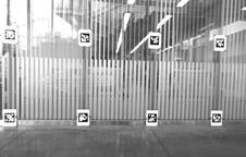
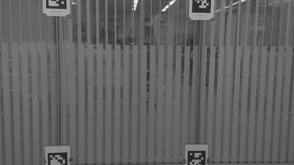
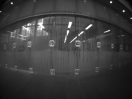
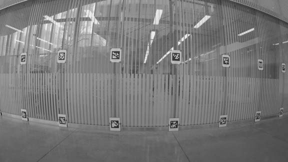
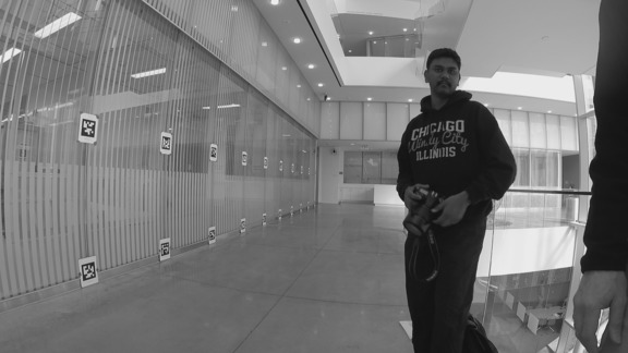
Extrinsic calibration method
The AprilTags on the north wall of the Singh Center were used as a calibration target. A total of 16 synchronized snapshots were cut from the video footage, and optical calibration was performed as described in the ICRA paper. As an example, here is a picture of snapshot #4. The complete set of images is available for download, as well as the locations of the AprilTags in that area.
 |
 |
 |
 |
 |
 |
 |
Notes on the VI sensor calibration
Although the VI-sensor has recorded the rectified images, they are in fact not rectified due to poor stereo calibration of the sensor. You will need to use the extrinsic rectification to get the proper camera-camera calibration. Alternatively, you can download a separate right/left image extrinsic + intrinsic calibration (done with Kalibr) from here.